Topographical Survey Equipment
As covered in last week's post, conducting a topographical survey prior to land development is crucial to the project's success. But what equipment do surveyors use, and how does it work? Discover the answers to these questions and more in the following article.
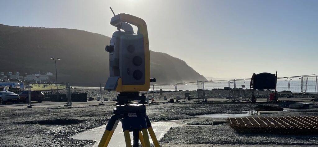
Introduction
The new world of surveying is a far cry from that of yesteryear, whose largely manual methods made true accuracy nearly impossible. These days, technology all but banishes imprecision, delivering a result that reduces as much potential human error as it does time.
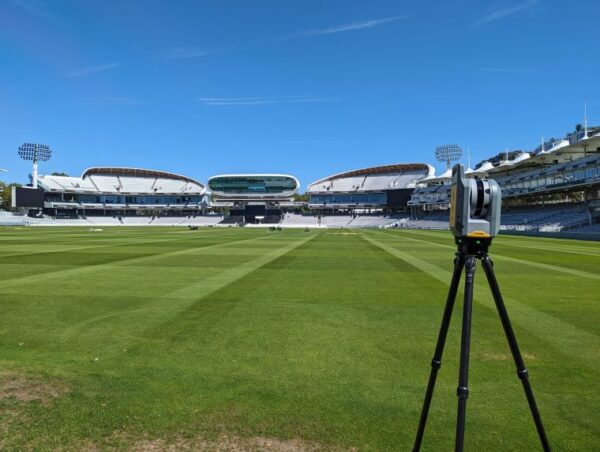
Consider Lord's Cricket Ground, of which Bury Associates undertook a survey. As with every topographic survey, we needed a comprehensive set of accurate measurements, including the boundaries, levels, and features of the specified land. This was to ensure that developers' plans were appropriate for the proposed site. Surveyors have always applied the same geometric principles to taking measurements, but prior to advancements in technology, conducting a land survey was a long and arduous process. The same instruments that are digitised today had manual equivalents. Rather than recorded automatically, data was written down on paper. Surveyors measured distances with tapes or metal chains instead of lasers.
These days, a surveyor's toolkit is very much more advanced, larger in size, higher maintenance, not to mention expensive! Clients save on time and money while gaining a better quality service.
Laser Scanner
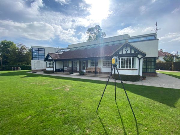
Laser scanning equipment captures a precise 3D representation of the physical environment. To obtain the data, the scanner emits high-speed pulses of light, which reflect off objects and return to the scanner's sensor. This is known as Light Detection and Ranging technology (LiDAR). The time elapsed between sent and received pulses is equal to the distance between the scanner and the object. This information is gathered as individual data points, each converted into a pixel with a known x, y, and z coordinate.
Laser scans are ranged around the site in different viewpoints and positions. Millions of data points are recorded and processed into a point cloud, creating an accurate 3D as-built data set of the area. The more data points a LiDAR scan collects from an area, the finer the detail that can be captured in the resulting 3D model. Each data point represents a specific location in three-dimensional space. When these points are densely packed, the model can accurately reproduce the shapes, sizes, and textures of the scanned environment, leading to a higher-resolution model. Despite the large volume of data recorded, the scan takes place at rapid speed. A higher scan speed allows for quicker data collection over a large area, which increases the efficiency of fieldwork, thus saving on costs.
Of a landscape, a laser scan displays the surrounding topography, both natural and man-made, including trees, streams, and fences. Obtaining a comprehensive portrait of the area as it stands is integral for planners to make informed decisions about their projects. For example, if a landscape has been shown to include dense forestry, developers can factor this into their decisions, rethinking the project by moving its location or working with conservationists to find a sustainable way forward.
LiDAR scanning is notable for its ability to penetrate through obstacles, such as vegetation, allowing for the mapping of surfaces hidden from direct view. This constitutes a significant improvement in the scope of surveying. Despite this, accuracy can vary based on the range of a particular scanner, the precision of the timing mechanism, and environmental conditions. For example, the presence of particulates in the atmosphere, such as dust, can scatter and absorb the laser pulses emitted, reducing the range and accuracy of the measurements.
Although for our purposes, I apply the benefits of LiDAR technology to surveying, the advanced technology has other uses, such as in autonomous vehicles, archaeology, and even Mars rovers.
A great example of a high quality laser scanner is the Trimble X7.
Total Station
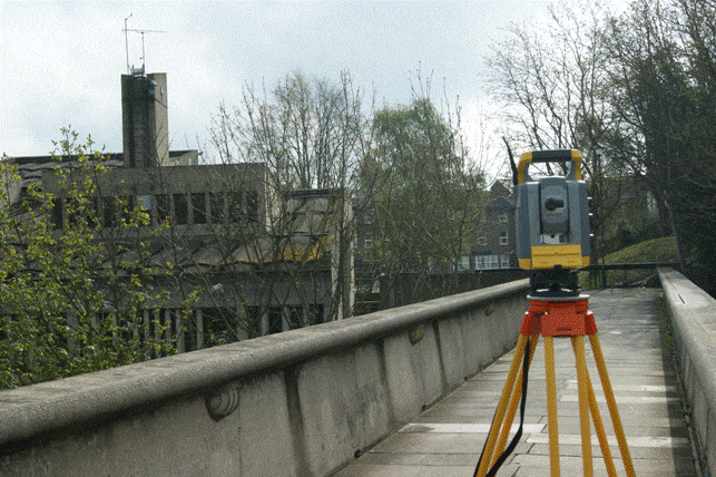
A total station is a sophisticated surveying tool that merges the functionalities of an electronic theodolite and an Electronic Distance Measurement (EDM) device. This instrument is capable of measuring angles and distances with high precision to determine the exact location of points in a survey area.
The theodolite feature of a total station comprises a telescope that can pivot along both horizontal and vertical axes. This allows surveyors to aim the telescope precisely at survey markers or specific points of interest. The high precision of the angles measured along these axes enables the calculation of positions with remarkable accuracy. Additionally, the telescope’s sightline can rotate up to 180 degrees. This feature, known as back-sighting, facilitates the verification of measurements by allowing angles to be measured again from the opposite direction, enhancing the reliability of the data collected.
EDM technology measures distances using the principle of electromagnetic wave reflection. It emits a beam towards the target, and the distance is calculated based on the time it takes for the beam to return or the phase change of the beam, depending on the technology used.
One of the key advantages of using a total station is its precision, able to measure angles to an accuracy of up to 0.5 arc-seconds. Depending on the model and conditions, distances can be measured with similarly high accuracy, making total stations indispensable for detailed surveying.
Data collected by a total station can be stored internally within the instrument or transmitted directly to an external data collector, allowing for immediate integration with design software.
One such high-tech model of Total Station includes the Trimble S7.
GPS equipment
The Global Positioning System (GPS) consists of a constellation of at least 24 satellites orbiting the Earth. At any given time, at least four satellites are visible from any point on the Earth's surface. The satellites transmit signals picked up by receivers on the ground, able to determine their location (latitude, longitude, and altitude) by calculating their distance from the satellites. This can provide positional accuracy within centimetres.
The three methods of GPS most commonly used by surveyors are as follows:
- Static GPS Baseline: This method simultaneously records the locations of both a known and unknown survey point for a relatively long period, ranging from 20 minutes to a few hours.
- Real-Time Kinematic (RTK) Observations: This setup comprises a central base-station receiver along with several portable devices. The base station transmits the observed carrier phase back out, and the portable devices then assess their own phase measurements against the broadcasted phase from the base station.
- Continuously Operating Reference Stations (CORS): This method utilises a network of permanent GPS stations that provide precise positioning data. These stations continuously collect GPS data 24/7, offering a framework for establishing highly accurate, geospatial reference systems over wide areas.
Total stations sometimes incorporate GPS technology to further enhance their capabilities of data collection. Otherwise, surveyors can employ the use of receivers, as well as additional equipment like a tripod for mounting purposes.
Drone technology
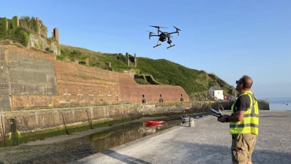
A drone survey employs an unmanned aerial vehicle (UAV) equipped with specialised sensors, including RGB (red, green, blue) cameras, multispectral cameras, and LiDAR payloads, to collect aerial data. This technique is highly effective for capturing detailed images of the ground from various angles. Each captured image is precisely tagged with its geographical coordinates, enabling accurate mapping and analysis.
The process utilises photogrammetry software to transform the collected images into geo-referenced orthomosaics, digital elevation models (DEMs), or three-dimensional representations of the surveyed area. These digital maps are instrumental for extracting vital metrics such as precise distances, areas, and volumetric measurements.
As the drone navigates over the project site, it employs its downward-facing sensors to systematically capture the landscape below. RGB cameras are primarily used for capturing high-resolution, colour images of the terrain, while multispectral cameras record data from different parts of the light spectrum. Drones equipped with LiDAR payloads can generate accurate 3D models of the terrain by measuring the distance to the ground with laser pulses, even in densely vegetated areas.
Modern drones are integrated with Geographic Information Systems (GIS) to enhance data visualization and mapping accuracy. Initially, drones were limited to data capture, requiring manual retrieval and analysis by operators. However, advancements in drone technology now allow for the real-time interpretation of data. This means that the raw data collected during the flight can be processed into actionable insights instantly, significantly enhancing the efficiency and applicability of drone surveys across industries.
This approach to surveying not only accelerates the data collection process but also improves the safety and accessibility of difficult-to-reach areas.
GPR and RFL equipment
Before initiating a project, developers may commission an underground utility survey to identify and map subsurface infrastructure such as pipes, cables, and sewers. This critical step ensures that environmental and structural constraints are considered early in the planning process, helping to reduce costs and minimise risks.
Underground utility surveys primarily employ the technologies of Radio Frequency Location (RFL) and Ground Penetration Radar (GPR) to detect beneath-the-surface utilities. RFL traces metal objects by detecting signals they emit, making it effective for locating metallic utilities like electricity cables. However, RFL requires the target to emit a signal, limiting its use to conductive materials.
GPR, on the other hand, sends high-frequency radio waves into the ground and detects signals reflected by subsurface objects or material boundaries. While GPR is less precise than RFL in determining an object's size or material, it is invaluable for locating non-metallic objects such as plastic pipes and fibre optic cables by capturing variations in reflected signals. The technique works for a range of materials, including plastic, concrete, and clay.
The effectiveness of GPR depends on the ground conditions and the frequency of the antenna used: higher frequencies yield finer detail at shallower depths, while lower frequencies penetrate deeper but with less detail. On average, GPR can reach depths of up to 30 metres, although this varies with the environment.
Conclusion
At Bury Associates, we utilise a range of different technologies to conduct our topographical surveys, from laser scanners to drones. Once we have all the information we require, our in-house team gets to work processing the data, producing custom deliverables. These can be Revit/BIM models, 2D/3D CAD drawings, and more, depending on the specific needs of our clients.
